


I'm a description. Click to edit me
Unit 3 Sketching
Essential Standard: 3.00
Apply sketching skills and techniques (Architectural & Engineering)
Apply Rough sketching (lettering for clarity, uppercase caps).
Indicator: 3.02
Apply sketching techniques and procedures
Apply 2D sketching – Single and Multi-view.
Indicator: 3.03
Apply 3D sketching – Pictorials (isometric, perspective, oblique).
Introduction: As instrument drawing becomes less prevalent in industry, the ability to create accurate technical sketches becomes more important. The curriculum team feels that it is critical for students to be able to communicate technical information through different types of sketches. This unit will cover the purpose of sketching, materials needed for sketching, techniques for sketching, importance of proportions, the types of sketches, and differences between isometric, oblique and perspective sketches.
Introduction to Sketching
What is a Sketch?
What is the purpose of a sketch?
What types of ways can I sketch?
What materials will I need to sketch?
Examples of Sketching:


Sketches can take the form of the following:
1. Design sketches - Design sketches are rough sketches that are used to quickly capture an idea. They tend to have less detail, structure and restrictions than freehand or technical illustrations.
2. Freehand technical sketches - Freehand technical sketches can be multiview or pictorial sketches. This type of sketch usually includes more detail and structure than design sketches. They also typically include dimensions.
3. Technical illustrations - Technical illustrations include more detail, structure, and restrictions than other types of sketches. The objective here is to create a sketch that looks as close to the final object as possible.
How do I start a sketch? What will I need?
When you create a manual sketch you will only use a pencil and a piece of paper (plain or grid). You will need a design problem to start with or an idea you want to sketch. When creating a sketch you will need structure, clarity and follow drafting techniques for sketching set by ANSI.
Techniques for sketching:
1. straight lines
2. angles
3. circles
Proportional Structure
1. Sketches must be proportional.
2. Use aids when sketching (pencil as measuring device to divide lines equally or proportionally)


Unit 3 Sketching Section 3.01
Indicator: 3.01 Apply Rough sketching (Communication).
Why do we need to sketch?
What material do I need when I sketch?
What is the purpose of sketching?
How do I make my sketches realistic?
Are there different types of sketching techniques? If yes what are they?

Communicate your sketch idea!
Good communication promotes clarity and understanding. A universal system of standards is needed to unify the drafting community. The American National Standards Institute (ANSI) provides a set of norms, standards and guidelines architects and engineer follow to provide unity.
Sketching an idea after brainstorming can some times be very difficult and might require multiple attempts. It is improtant to observer guide lines established for lettering, line structure and proportion. Below is and explanation of the structure we will follow.
Lettering
Vocabulary
Font- A specific style of lettering
Clarity- Information communicated without misunderstanding
Uniform- All the same or similar characteristics that makes items look like they belong together.
ANSI Drafting Standards:
Font Style: Gothic (Franklin Meduim).
All Capital letters at a height of 1/8" (.125")
Spacing between all words are equal to the letter "O".
Vertical and horizontal spacing between letters must be uniform.
All letters, numbers and fractions must be uniform in apperance.
All drawing text must be clear.

Guided Practice
Materials:
1. Pencil
2. 8.5x11 sheet of grid paper (click here for graph paper PDF)
Directions:
- Student will practice writing the letters of the alphabet and numbers on the grid paper provided or by downloading and printing the graph paper above.
- Student will write each letter according to the ANSI Drafting Standards above.
- Student will replicate each letter and number 10 times in a single box horizontally.
To the right is an example of a student working on the assignment.

Writing Assignment
Materials:
- Title Block Image (Click here to download)
- Blank title block
- Pencil
Directions:
- Students will replicate the text in the title block image to the right using the blank title block sheet handed out.
- Students must follow the standards set by ANSI
- Students will be able to use vertical and horizontal guide lines if nescecary.
-Use all capital letters
-Use Gothic Font
-All letter strokes should be from top to bottom left to right


Unit 3 Sketching Section 3.02
WARRANTY
I'm a paragraph. Click here to add your own text and edit me. It’s easy. Just click “Edit Text” or double click me and you can start adding your own content and make changes to the font.
Indicator: 3.02
-
Apply sketching techniques and procedures
-
Apply 2D sketching – Single and Multi-view.
In this section of sketching you will be learing the procedures and techniques to create a clear and effective sketch. You will learn how to draw straight, curved and angled lines. You will learn about single view drawing and multi-view drawings. At the end of this section all student will be able to draw sketches with proprotion, clear lines and effectively communicate ideas via pencil sketch.
Vocabulary
Proportion- When the parts of a drawing relates in size to the whole drawing
Bisect- When you cut an angle in half. Example: When you bisect a 90 degree angle you get a 45 degree angle.
Subdivide- It occurs when you bisect an angle into multiple parts. When you subdivide a 90 degree angle you get two equal parts.
Single View 2D- One view of an object
Multi-view 2D- Multiple views of an object (More than one side)
Octagon- Eight sided polygon
Hexagon- Six sided polygon
Pentagon- Five sided polygon
Radius- Distance from center of a circle to any point on the outside edge of the circle
Diameter- Distance from outside edge to outside edge of a circle through the center point of the circle.
Sketching Techniques and Procedures
Freehand sketching straight or curved lines can be difficult to draw if you haven't sketched before. But with a little practice you can create clear consistant lines that will communicate your ideas effectively. Below you will practice drawing straight, curved and angled lines that will appear in single and multi-view drawings. All sketching will be done with only a pencil and a piece of blank or graph paper. No straight edges, rulers or any drawing aids can be used.
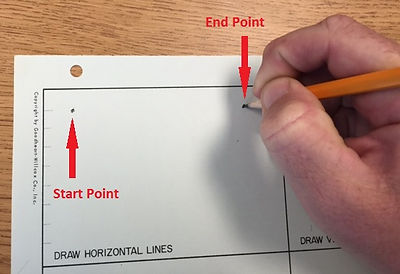
Sketching Straight and Angled lines: When you are sketching straight line, first ceate a start and end point by drawing a dot for the start point and a dot for the desired end point. Connect the dots by concentrating on the end point. See example to the right.

Guided Practice
Materials:
1. Pencil
2. 8.5x11 sheet of pratice paper #1 (click here for practice paper PDF)
3. 8.5x11 sheet of pratice paper #2 (click here for practice paper PDF)
4. 8.5x11 sheet of pratice paper #3 (click here for practice paper PDF)
Directions:
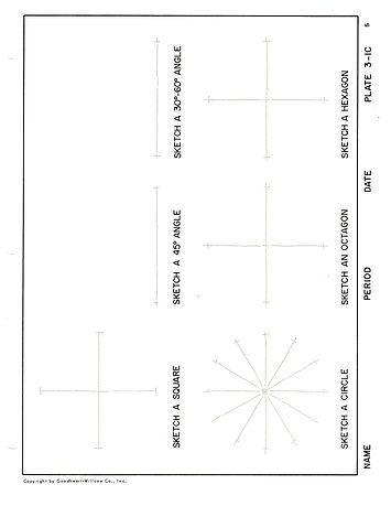
- Students will practice drawing horizontal and vertical lines
- Students will practice sketching lines at a 45 degree angle
- Student will practice sketching a circle
- Students will practice drawing polygons


Practice Paper #1
Practice Paper #2
Practice Paper #3
Independent Sketching
Directions:
- Students will download the sketch paper (Click here) for each of the sketches
- Students will draw sketch 1
- Students will draw sketch 2
- Students will draw sketch 3
*Try and copy the sketch by using the graph paper lines as a guide.


Sketch #1
Sketch #3
Sketch #2
Single View Sketching
When you are creating a single view sketch you are just drawing one side of the feature. The image would be considered 2 Dimensional because it would only show two of the three dimensions (Height, Width, Depth). For example if you were just drawing the front of your house, you would be sketching only the height and width features of front of the house. You would not be able to see the depth of the house in your single view sketch.
Normally when architects and engineers sketch a single view drawing they use a process called orthographic projection. That is were sides of a three dimensional object are projected out at a 90 degree angle. See the examples below.

Example 1

Example 2

Independent Single View Sketching
Directions:
- Students will use an computer paper for each sketches
- Students will draw SV Sketch 1
- Students will draw SV Sketch 2
- Students will draw SV Sketch 3
*No straight edges or guides can be used while sketching.


SV Sketch 2
SV Sketch 1
SV Sketch 3
Multi-View Sketching
When you are creating a multi-view sketch you will create multiple sketches of more than one side of an object. If we can visualize a 3D cube you will be able sketch the size standard sides. Front, Top, Right side, Left side, Back and Bottom. While the cube has three dimensions the sides of the cube will only have two dimensions. If you look at example 1 below you will see we start with a 3 dimensional cube. As we move to the right we unfold the cube so that it is completely flat and we can see all six sides. This is unfolding of the cube produces a set standard order of views. See example 2.

Example 1

Guided Practice
Materials:
1. Pencil
2. 8.5x11 sheet of graph paper click here
Directions:
- Students will practice drawing the front, right side and top of each 3D object.
- Students will practice lining up the views in the standard order.
*You will not be able to use a straight edge or any other aid when sketching the views. Use the graph lines to aid in the sketch constructions.
Solution:
