
-Heritage High School Wake Forest, North Carolina-
Engineering III
Contact Mr. Riedel:
Constraint-Based Parametric Modeling
003.
Demonstrate the concepts and principles of constraint-based
parametric solid modeling
003.01
Explain the terminology related to constraint-based/parametric
solid modeling
003.02
Explain the concepts related to constraint-based/parametric solid
modeling
003.03
Create solid models using a constraint-based/parametric solid
modeler

Introduction: The purpose of this unit is to give a foundation for the topic of constraint-based or parametric solid modeling. Over the last decade, computer-aided design technology has drastically changed in the area of 3D modeling. No longer is the drawing the primary means of communication between the designer and manufacturing when producing metal or plastic parts. In fact, some companies go directly from the 3D data produced by the designer or engineer to the final part. This is done by transferring the 3D data to computer numerical control (CNC) machines or sending the data to have molds developed for forming plastics.
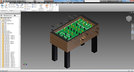
SolidWorks®, SolidEdge®, Inventor®, Pro/Engineer®, and ProDesktop® are constraint-based CAD programs. They all function in a similar fashion. The biggest difference between these programs and software such as AutoCAD® is the way they take advantage of the 3D database. Within the constraint-based modeler environment, the 3D solid model or part is typically the first type of file that is created. Once the part files are created, assemblies and drawings of parts can be generated. Most of these programs take advantage of bidirectional associativity between the files. In other words, if a dimension is changed in the model, the drawing file and assembly files automatically update. If a change is made in the drawing file, the change is reflected in the part and/or assembly files. As you can probably imagine, this type of environment for designing parts is much different than laying out 2D drawings. Students who can master this type of software will be much more efficient and productive.