
-Heritage High School Wake Forest, North Carolina-
Engineering III
Contact Mr. Riedel:
Defining Constraint Based Modeling
Constraint-based modeling software – constraint-based modeling software is a type of CAD software that uses feature definitions (extrude, revolve, fillet, etc.), dimensional and geometric constraints (equal, parallel, concentric, etc.), and a feature tree (how the features are arranged) to define 3D solid models. See Figure 1 for an illustration of the different types of files with a constraint-based modeler.
Part file – [.ipt] a part file is an individual solid model file within a constraint-based CAD system. A part file contains information about the part’s 2D and 3D geometry, appearance, material properties, and annotations or notes.
Assembly file – [.iam] an assembly file is a type of file used within a constraint-based CAD system to organize individual parts and/or assemblies to create a more complex representation of a product. Assembly files contain information about how parts are constrained relative to one another.
Drawing file - [.dwg] a drawing file is used to create traditional 2D documentation of objects within a constraint-based CAD system. Drawing files typically include traditional views (top, front, right-side, bottom, left-side, rear, auxiliary, sectional, and pictorials), dimensions (standard, tolerance, and geometric), and annotations or notes (including titleblocks and borders).
Construction plane or Workplane – construction planes or workplanes are the most common type of construction geometry within constraint-based CAD systems. They are planes in 3D space used to define global (world) and local (user defined) coordinate systems. They can be imaginary planes or surfaces on the existing solid model.
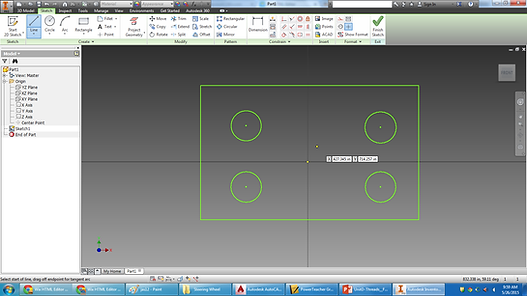
Sketch or Profile – Within the context of constraint-based modeling, a sketch or profile is the 2D geometry created on a construction plane or workplane which is used with some type of sweeping operation (extrude, cut-extrude, revolve, cut-revolve, loft, sweep, etc.) to create a solid model.
Feature – a feature is a physical portion of a solid model that appears in the feature tree. Features can be extrudes, revolves, sweeps, lofts, fillets, chamfers, etc. H. Feature definition –feature definition is the method a constraint-based CAD system uses to keep track of the parameters for each individual feature that makes up a solid model. Swept features are defined by a construction plane or workplane, a sketch or profile with dimensional and geometric constraints, a path or direction, and a distance or angle. Other features such as fillets, chamfers, and shells are not defined by a sketched profile but by other parameters usually selected from a dialog box within the software.
Feature tree – a feature tree (sometimes called a browser, modeling tree,
history, or feature manager design tree) is a list of the geometric features
that exist within a model file in the order in which they are interpreted by
the modeler.
Features in the tree can be:
-
Part Name
-
Construction geometry (origins, planes, axes, etc.)
-
Work Planes (YZ, XZ, XY)
-
Axes (X, Y, Z)
-
Part features (extrudes, revolves, sweeps, lofts, fillets, etc.)
-
Components in an assembly file. **Not Shown in adjacent image
Constraints – constraints are the mathematical requirements placed on the geometric elements in a 3D solid model. They control the geometric behavior of a dynamic solid model.
Implicit constraints – implicit constraints are constraints which get applied automatically by the software when the user sketches lines. Examples of common implicit constraints are the horizontal and vertical constraints that are applied to lines when they are sketched.
Explicit constraints – explicit constraints are constraints which the user must apply by completing some type of command action.
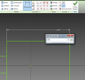
Dimensional constraints – dimensional constraints are the dimensions that are applied by the user to a sketch. They define distances between two points or features.
Geometric constraints – geometric constraints are constraints that define relationships between geometric elements. For example, two lines may be defined as parallel, equal, or collinear (in the same line).
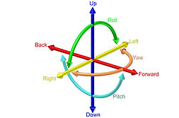
Degrees of freedom – degrees of freedom define the manner in which an object can move. Each object has six degrees of freedom; 3 translational (linear movement along the X, Y, or Z axes) and 3 rotational (rotation about the X, Y, or Z axes).
Design intent – design intent is a term used to describe how feature definitions and constraints are used to control the 2D and 3D geometry of a solid model in a predictable manner.
Bidirectional associativity – bidirectional associativity is a term used to describe the relationship between part, assembly, and drawing files within a constraint-based solid modeler. Within constraint-based modelers that have bidirectional associativity, changes to any of the files (parts, assemblies, or drawings) are automatically updated in ALL linked files (eg. a change to the part file automatically generates changes to the assembly and drawing files or a change to the drawing file automatically generates changes to the assembly and part files).
Unidirectional associativity – Within constraint-based modelers that have unidirectional associativity, changes to a part file automatically generate changes to assembly and drawing files, but not vice versa. Which means you cannot make changes


Features
Axes
Work Planes
Part Name


Constraint Panel


Fully defined geometry is located relative to the part’s origin.
i. Vertical
ii. Horizontal
iii. Parallel
iv. Perpendicular
v. Tangency
vi. Concentric
vii. Collinear
viii. Coincident
ix. Symmetry


