Email Mr. Riedel: jriedel1@wcpss.net
World Coordinate System (WCS)
All objects in a drawing are defined by their coordinates in the World Coordinate System (WCS), which cannot be moved or rotated. The WCS and the UCS are initially coincident in new drawings.
Identified by the WCS Icon which has a box at the origin the lower left hand of the AutoCAD Drawing Screen.


2D UCS Icon in CAD
3D UCS Icon in CAD
User Coordinate System (UCS)
-
The XY plane, also called the work plane, on which objects are created and modified
-
The horizontal and vertical directions used for features like Ortho mode, polar tracking, and object snap tracking
-
The alignment and angle of the grid, hatch patterns, text, and dimension objects
-
The origin and orientation for coordinate entry and absolute reference angles
-
For 3D operations, the orientation of work planes, projection planes, and the Z axis for vertical direction and axis of rotation
You can change the location and orientation of the current UCS by clicking the UCS icon and using its grips, or with the UCS command. Display options for the UCS icon are available with the UCSICON command.


WCS Icon Symbol
2D WCS Icon in CAD
3D WCS Icon in CAD
Click on Image to Enlarge

Creating a New UCS in AutoCAD
(Reference the image to the right)
1. Click on the WCS Submenu button underneath the view cube.
2. Click on the New UCS button then in the drawing area select a new coordinate origin.
3. Select by manually clicking the direction you want the X-axis to go.
4. Select by clicking the direction you want your Y-axis to go.
Click here for the video lesson
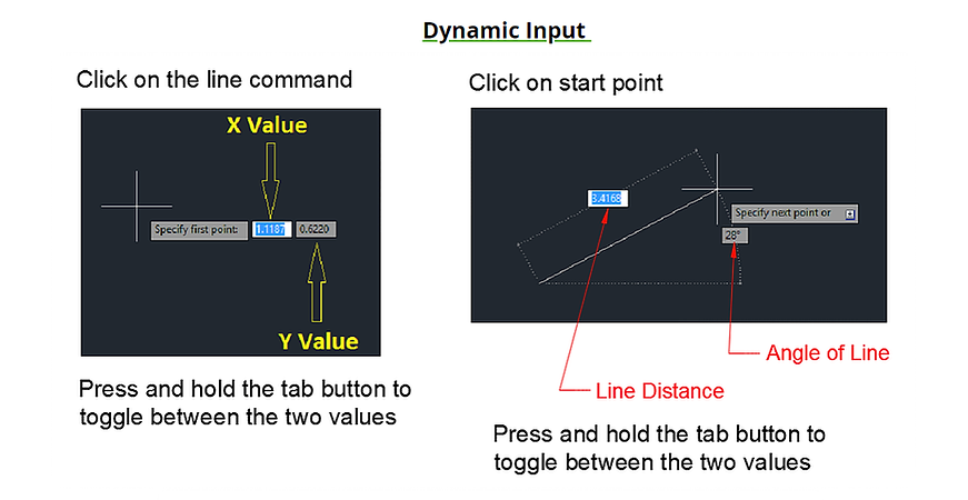
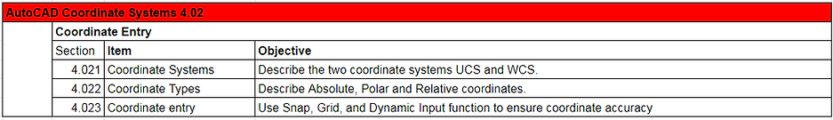
Coordinate Entry


4.021 Coordinate System
Coordinates
The Cartesian Coordinate System is a coordinate system that specifies each point uniquely in a plane by a pair of numerical coordinates. Coordinates are a group of number set at a specific distance from an established origin. The origin is the location in the coordinate system where the X, Y and Z axes intersect. Coordinate distances move specifically along the X, Y and Z axes. Coordinates can look like this: X , Y, and Z or in actual form 6,7,9.


X axis Directions
Width (Side to Side)
Y axis Direction
Top to Bottom

Z axis Direction
Front to Back
Absolute Coordinates
A series of numerical positions (X,Y) that are calculated from a fixed point of origin. The origin will never change locations and will be a point of reference for all coordinates.
Polar Coordinates
A system of coordinates for locating a point in a plane by a distance and an angle from a defined origin.
@Distance<Angle
@8.5<45
Relative Coordinates
Allows you to specify a position along the X-axis, Y-axis, and Z-axis (if needed) to locate a point relative to the last point you specified.
Each new point is calculated from your current position.
Example:
@X,Y
@1,2


Line Angle in Degrees


Polar Coordinates Example 1
Polar Coordinates Example 2

Current Position Becomes 0,0
4.022 Coordinate Types
4.021 Coordinate Entry
Grid Function
Grid lines- Rectangular pattern of lines or dots separated by a given distance. In AutoCAD grid lines will not be printed. The grid is used to aid in alignment. It is also used for visualizing distances.
Minor Grid lines- Are the grid lines that are not as visible as the major grid lines and spaced by assigned input.
Major Grid lines- Grid lines that are most visible and are spaced farther apart then minor grid lines.
Grid Mode- Located on the Status bar
Snap Function:
When Snap is turned on the cursor can not move freely. Snap function restricts the movement of the cursor by jumping from point to point up/down and left/right. The distance the cursor jumps will be the same in the X and Y direction. Snap mode aids in drawing accuracy.


Grid and Snap Button location on Status Bar

Grid Snap
The Triangle button accesses the sub menu options